Historic monument and archaeological site 3D reconstruction is nowadays often required for many applications (scientific and architectural studies, virtual visits for a better understanding of the monument, etc). This task is very time-consuming. Automating the modelling of the most common components could ease this 3D work and produce accurate, consistent and re-usable models. Based upon compound rules of architectural elements but also upon various other data sources such as 2D plans, photographs and 3D laser scans, we have conceived and developed an interactive tool for virtual 3D reconstruction of heritage monuments. It allows a quick modelling and accurate adjustments to the measured data. This tool could be a great help for architects and archaeologists. Research first has began with the study of classical architecture, and has gone on with other architectural styles. Architectural elements are described with parametric data, then generated by our tool.
Retour menuArchitectural components (moulding, vault, door, window... and also sculptured elements) are described by their own parameters in a file library. As an example, a Doric column and a Corinthian one are both described with the help of the moulding object, only the parameters are different. They are both described in a file. Several files can be used for describing the same Doric column for different theorists (between Vitruve, Vignole or Diderot one can find several little differences in the theoretical descriptions).
When the user chooses an object predefined in this library (by means of a menu in the user interface), it is created by POG in real time with the parameter values read in the file. It can then be adjusted by modifying the parameters to adapt the shape to the various practical situations. Parameter adjustments (with the help of 2D plans, photographs and laser point clouds) let us obtain a 3D model close to the real object. Surfaces of the 3D rebuilt scene or the architectural objects and their parameters can be saved in a file. In the second case, the file can be added to the library.
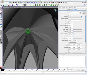
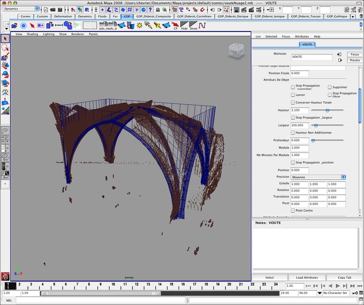
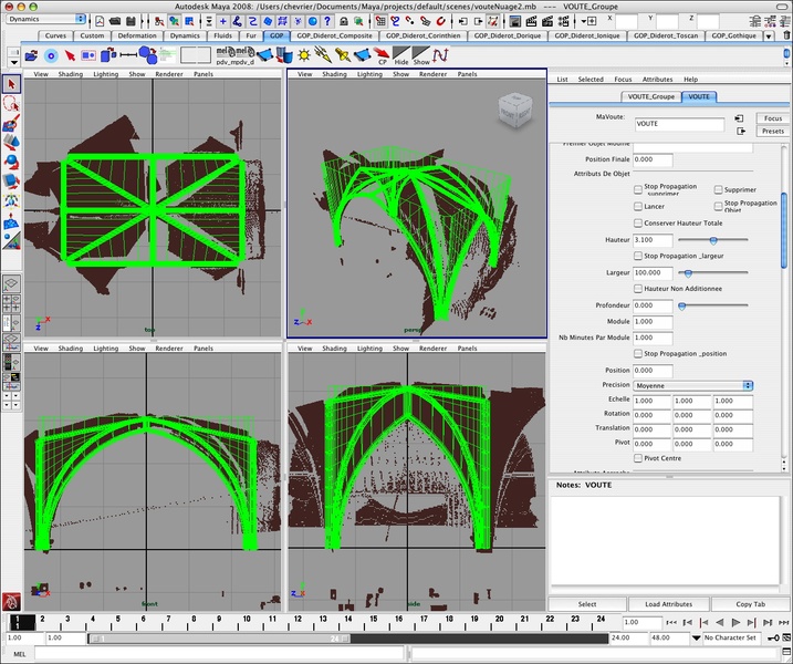
The software development has been performed in the Maya environment in MEL and C++ language. Maya allows the adding of some plugins and menus to the graphical user interface. A Maya object is described by a set of attributes that appear in a window (the attribute editor) when the corresponding graphical 3D object is selected in the scene. When an attribute is modified, the â����computeâ���ù method is called and the object can be generated again with the new values of the parameters. To each of our architectural components corresponds a Maya object, to each parameter corresponds a Maya attribute. Furthermore Maya allows the use of all the modeller functions and possibilities for the sculpture creations, specific adjustments and deformations in the shape (erosion, breaking, non perfect shapes). Finally Maya is not only a modeller but also a computer graphic image generator that can be used for various uses: archaeological presentation as it was in the past, 3D scenery for movies and much more.
Retour menuThe use of various data: 2D plans and pictures (selection of pixels) or 3D laser scanning (selection of cloud points) allow the positioning of the architectural element in the 3D scene. Another way to position elements in the scene is the use of a hierarchical description and relative positioning.
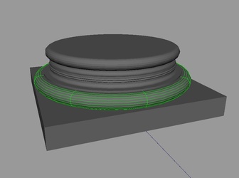
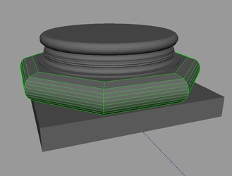
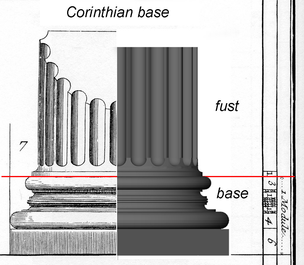
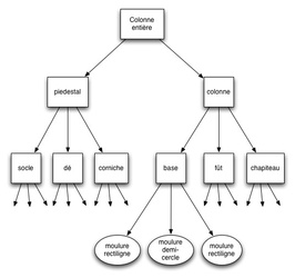
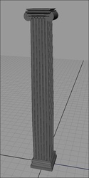
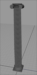
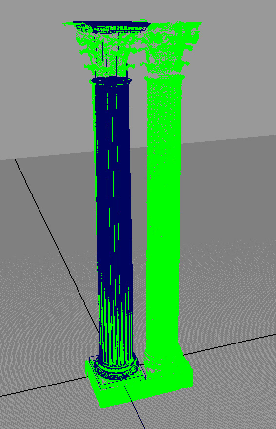
HIERARCHICAL DESCRIPTION: A monument is composed of various architectural elements. Each of these elements can be split in several parts again, so that we finally identify simple elements. Let's take the case of a column (Figure 1): this is composed of its pedestal, and of the column itself. The former is composed of a scamillus, a die and a cornice. The latter is formed with a base, a fust and a capital. Each of these elements is itself composed of several mouldings. Thus the entire column can be represented in a hierarchical manner and the same hierarchy is used to describe the column in the file library. In the same way, a building is an organisation of columns, cornices, doors, windows, pediments, sculptures, etc that can be described hierarchically and with notion of relative positioning (following part).
In Maya, Objects can be hierarchically organized. However neither the ascii file format nor the MEL (Maya Embedded Language) are simple and easily readable. They are mostly composed of command lines and it is not easy to describe the creation of nodes or a hierarchical scene. That's why we choose another description language, the Open Inventor file format (i.e. VRML 1), in order to describe the hierarchy and the parameters of architectural elements. The representation of the component hierarchy is really simple. The values affected to each parameter are clearly visible.
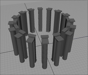
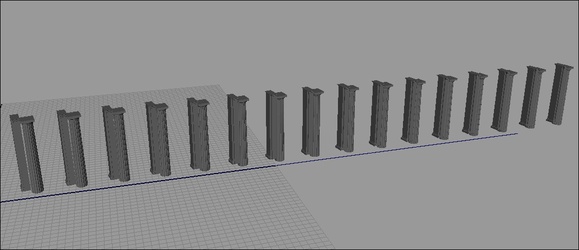
A special node allows grouping elements and the other nodes of the hierarchy are architectural elements (vault, door...). Complex shapes, like pediments, have their own parameters (shape, dimensions, oculus...) and have also some child nodes to describe the moulding profiles. A window has the following child nodes: a balcony node, a pediment node. Grouping nodes have parameters common to all nodes (global dimensions and positioning parameters). These parameters can be set for the grouping nodes and they will be transmitted to the child nodes by a propagation mechanism. Every modification of one of these parameters is also transmitted to the child nodes and the corresponding 3D objects are recomputed. These parameters are for instance the value of the module, the number of minutes per module, revolution or extrusion parameters (Figure ), duplication parameters (Figure ). Every moulding of a column is a revolution shape, so this parameter is only once specified in the grouping parent node. Each object (leaf or grouping node) can be linear or cicular instanciated to form a set. The volutes of the Corinthian capital form a four instance circular set. The dentils of the pediment form a polyline set with the required number of instances (automatically computed) to cover the path. One set can be inserted in another set: a Corinthian column with its four volutes can be globally instanciated to create a column set.
Architectural elements are built in 3D in a local coordinate system from their parameters and then are positioned in the scene according to their neighbours. They have to be correctly laid out to form the monument. This positioning is also indicated in the parameters of the nodes. The next section explains how we tackled this aspect.
Positioning of components is done as simply as possible in a relative way with respect to the other components. No computation has to be performed by the user. Four kinds of positioning can be used: the stacking (mouldings are stacked to form a column) ($ 3.2.1), the anchoring to a component point (a sculptured key is positioned in a vault) ($ 4.2.2), the relative positioning to the bounding box of another component (a door at the right of another door) ($ 4.2.3) and the relative positioning to the bounding polygon (the second edge of one element is close to the fourth edge of another one) ($ 3.2.4). A positioning parameter modification of an element leads not only to the rebuilding of the 3D position of this element, but also of all the elements depending on this object if they are affected by the modification (i.e. if it modifies their location or orientation). For all kinds of positioning, attached components can be simple architectural elements or grouping nodes.
3.2.1. : Stacking: Column mouldings are stacked on top of eachother according to their height. It is the same for every element that has a specified height (3D representation and not only a grouping node). The first floor is over the ground floor. Modification of the height of one of the elements affects the followings components. By the mechanism of propagation the following elements are automatically repositioned.
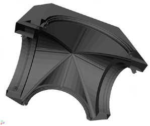
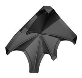
3.2.2. Anchoring to a Component Point: A component C2 can be attached to another component C1. During the creation of C1, special points are automatically specified as potential anchoring points for other components. For example, an anchoring point is defined at the vault keys (Figure 3a), or at the door key (the horse sculpture in Figure 3b). A parameter in C2 indicates that it is anchoring to C1.
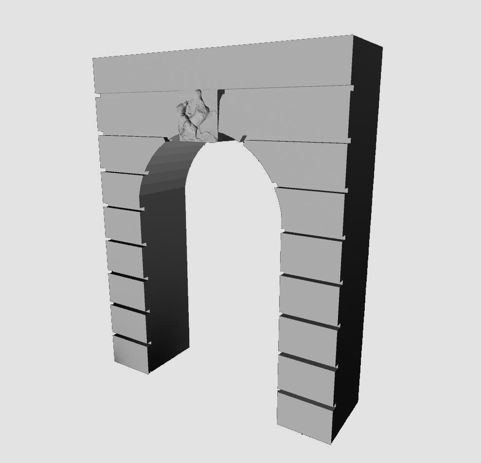
3.2.3. Relative Positioning to the Bounding box A component C2 can be in front of, behind, to the left of or to the right of another component C1. Above and below correspond to the stacking (case 1). The bounding box of each component is automatically computed during the creation of the 3D object and does not necessarily correspond to the real 3D bounding box. For instance, the key-door sculpture comes in front of the main part of the door and is not pertinent for the relative positioning. It can even alter the result if we want to attach another door, the main surfaces have to be at the same level. However, if needed, the component C2 can be translated with a parameter if its position has to be adjusted. As in the previous case, a parameter in the C2 element indicates that it is attached to C1, and a second parameter specifies the relative position (front, behind, left, right).
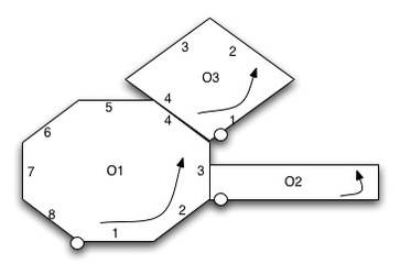
3.2.4. Relative Positioning to the Bounding polygon A C1 component side can be attached to a C2 component side. As in the previous case, the bounding polygon is computed during the creation of the 3D object and does not necessarily correspond to the real bounding polygon. We are just interested in the 2D horizontal polygon. Polygon edges are numbered from the lowest left point. A parameter in component C2 specifies which edge of C2 is attached to which edge of C1. C2 has to be rotated so that its chosen edge is in the same direction as the C1 chosen edge.
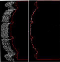
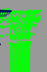
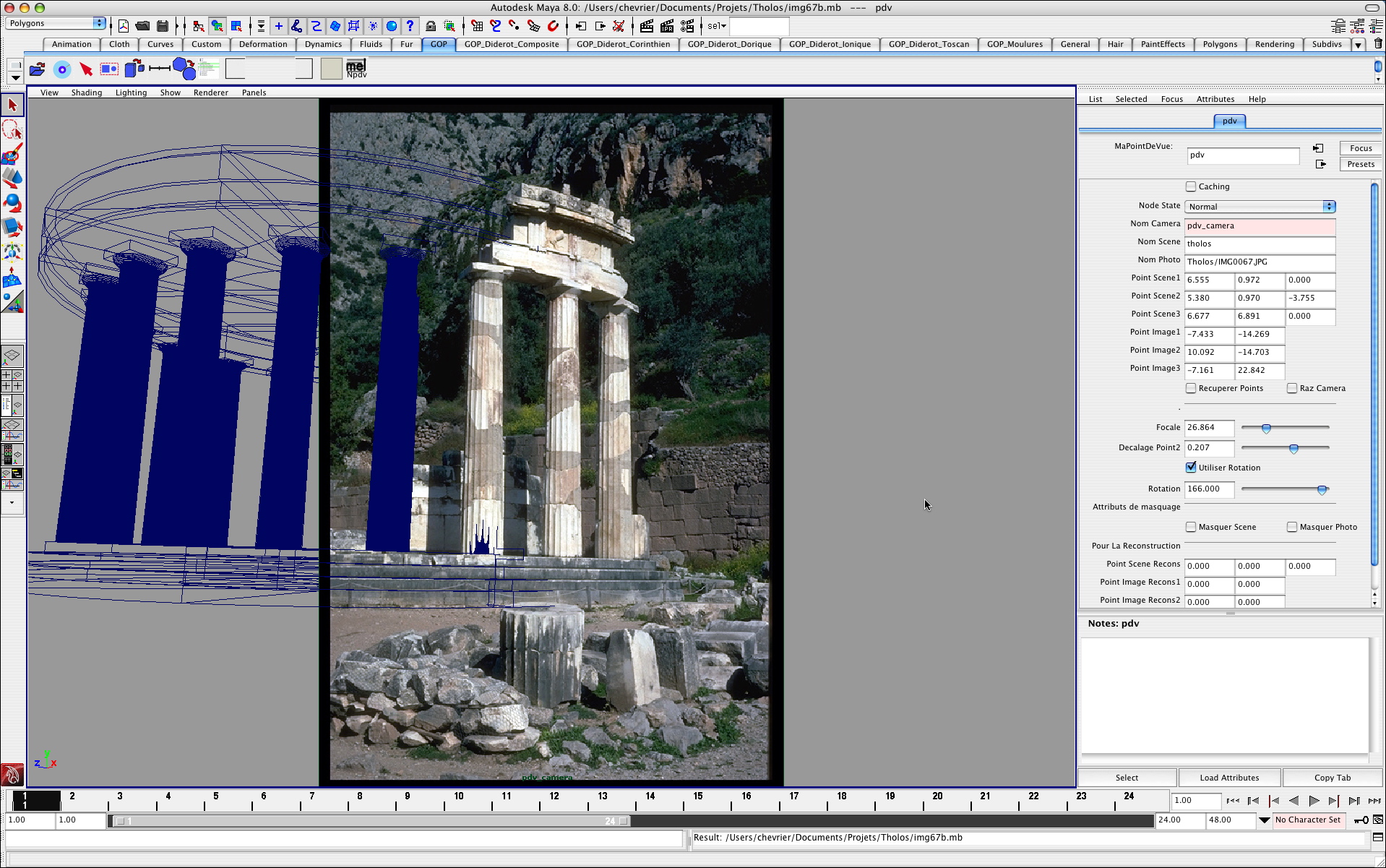
Automatic adjustment of the architectural element to the point cloud is not undertaken as it could lead to wrong modelling: we are dealing with complex shapes and point cloud often contains noise due to measurement errors and modifications of the imperfect scanned shape (damages by erosion, breaking...). It is then difficult to distinguish small elements like thin moulding profile for example (Figure 3). For ancient, classical and also Khmer styles, theory is almost respected in the existing buildings and is then a great help for the modelling process. On the other hand, gothic style monuments have their own specificities according to theory: theoretical values have to be adjusted with the help of the point cloud (vault, pillars...).
Points of the cloud can be selected. Two points are selected to define a bounding box. If required, a rotation can be specified to orientate the bounding box. Then the user selects the architectural component (which can be a single element or a compound of elements) he wants to build (for example a Doric column according to Vignole). The component is then automatically built by adapting its global dimensions (here the total height of the column) to the selected points and by positioning it in space. In this case, only the height is taken into account because the entire mouldings of the column are described according to a module. For other architectural element (the gothic vault for example), the three dimensions are taken into account for the reconstruction. Then all the parameters can be adjusted by the user to better fit the point cloud.
Most 3D reconstruction projects only dispose of photographs, since laser scanning is still expensive and time consuming. Pictures are taken into account in two different ways: with the viewpoint recovery (part 6.1) or with an upright picture (6.2).
The first step is to select 2D points in the pictures to create the associated 3D points. Then these 3D points are used in the same way as the range data points (part 4). We use two different methods:
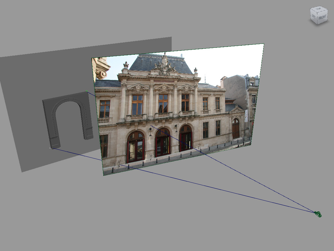
Use of a point on the image plane and of a 3D construction plan. The user positions a plane in the 3D scene and selects points in the image plane. 3D corresponding points are then constructed on the plane: it is the intersection of the line [viewpoint, 2D image point] with the plane (figure).
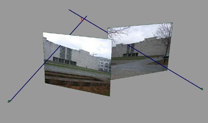
Use of several pictures On two or more pictures, the same corresponding image point is selected (called Pi). With the known camera positions (called Ci), straight lines are defined (PiCi). Theoretically, these lines intersect at one point. In practice, with two lines, the shortest distance between the lines gives a small segment, on which the user can locate the 3D point. If we dispose of more than two pictures, by taking them two by two, we can define various segments, defining a small 3D space where the 3D point can be situated (Figure 5). If we have a point cloud, this small area is a help to find a point in the cloud. It is a future work to automatically search in the point cloud the points closest to the segment or inside the small area.
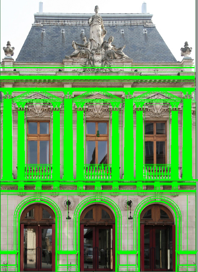
Dxo software also allows a manual righting of pictures, so that they can be used as a support for a 3D reconstruction according to orthogonal projection.
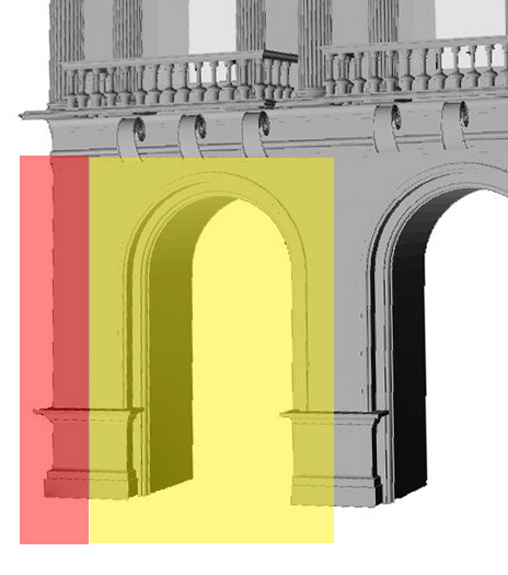
Let's take an example of a facade (see figure). A rectangle with the same ratio as the picture and the same dimensions as the existing facade
is positioned by the user in the scene where we want to build the facade. This rectangle is textured with the upright picture and points in the picture can be selected to
create the parametric component on the 3D rectangle. The depth position component can be adjusted with the parameter components (for example, the two columns on each side
are in front of the door plan). This technique is less accurate than the other because we use the picture as if it was an orthographic projection but it is not.